SAP PI-통합 구성 생성
이제 통합 구성을 만드는 방법을 이해하겠습니다.
다음 단계를 수행하십시오-
Step 1 − Object → New → Under Collaboration Agreement → 통합 구성으로 이동
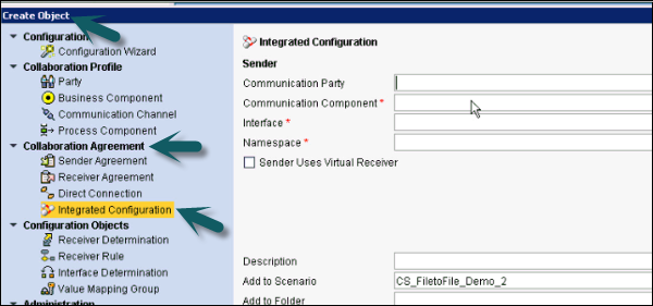
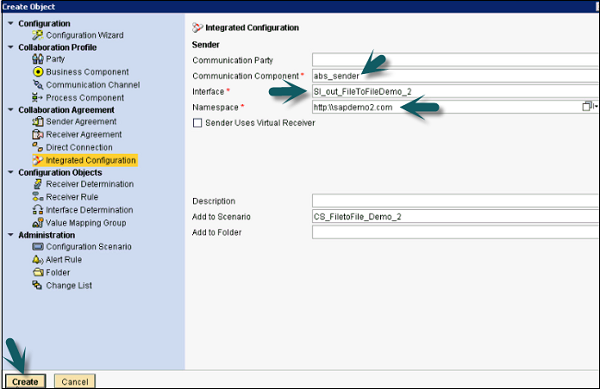
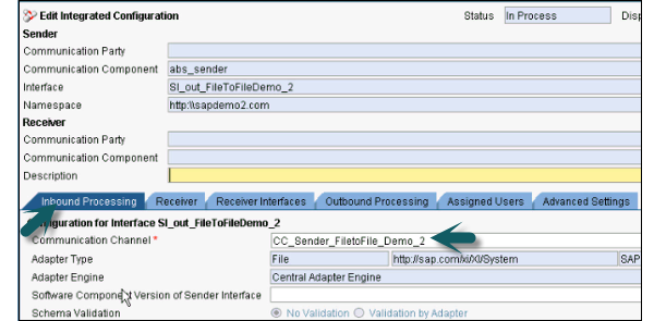
Step 2 − 통신 컴포넌트에 앞서 사용한 발신자 컴포넌트를 입력합니다.
인터페이스는 이전 단계에서 ESR에서 생성 된 아웃 바운드 프로세스와 동일한 서비스 인터페이스 이름입니다.
네임 스페이스는 이전 단계에서 ESR에서 생성 한 것과 동일한 네임 스페이스입니다.
딸깍 하는 소리 Create 단추.
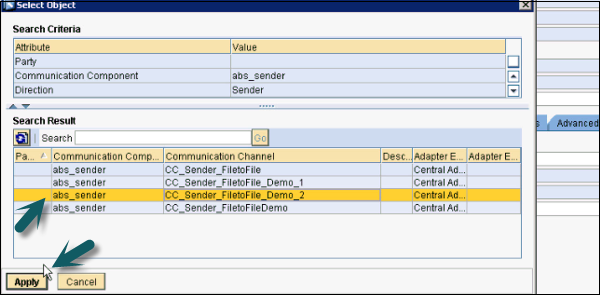
Step 3 − Inbound Processing 탭에서 보낸 사람에 대해 생성 된 통신 채널을 선택합니다.
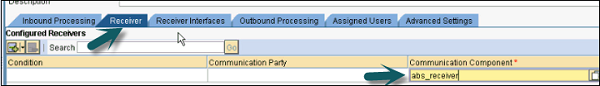
Step 4 − 수신기 탭에서 다음 스크린 샷과 같이 통신 수신기를 선택합니다. −
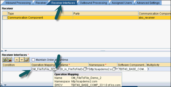
Step 5− Receiver Interfaces 탭으로 이동하여 Operation Mapping을 선택합니다. 검색을 클릭하고 다음 스크린 샷에 표시된대로 작업 매핑을 선택합니다. 작업 매핑은 이전 단계와 동일한 방식으로 생성됩니다.
Step 6 − Outbound Processing 탭으로 이동하여 Receiver Communication 채널을 선택하십시오.
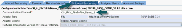
Step 7 − 위에서 언급 한 설정을 마치면 Save 과 Activate 상단에.

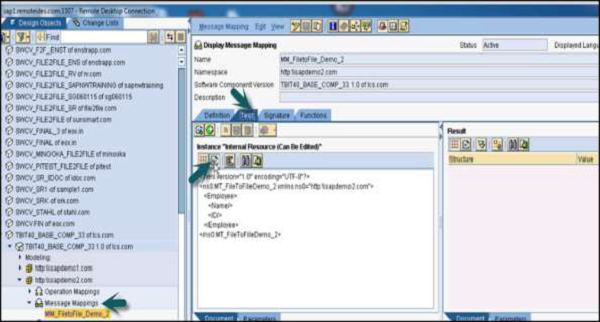
Step 8− sample.xml 파일을 아웃 바운드 폴더에 넣습니다. ESR의 메시지 매핑에서 샘플 xml 파일을 가져올 수 있습니다. ESR → 메시지 매핑 → 테스트로 이동합니다.
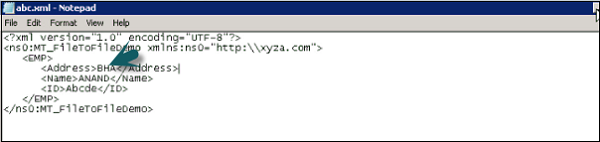
Step 9−이 샘플 파일에는 데이터가 없습니다. abc.xml 파일을 만들고 샘플 xml을 해당 파일에 붙여 넣습니다. 다음 스크린 샷에 표시된대로이 xml 파일에 일부 데이터를 추가해야합니다.
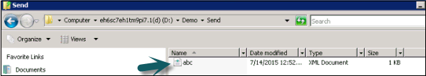
Step 10 −이 파일을 Send folder 구성시 디렉토리 및 파일 구성표에 언급 된대로.
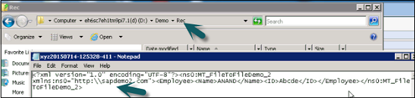
Step 11 − 다음으로 이동 Receiver folder 그리고 그 안에 데이터가있는 xml 파일을 볼 수 있습니다.
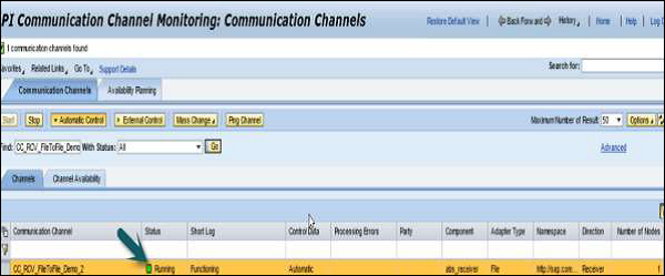
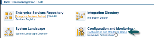
Step 12 − 어댑터 엔진 → 통신 채널 모니터를 모니터링하려면 구성 및 모니터링 홈으로 이동합니다.
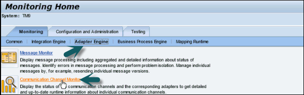
Step 13 − 어댑터 엔진 → 통신 채널 모니터로 이동합니다.
Step 14 − 통신 채널 복사

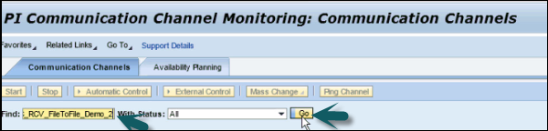
Step 15− 파일 대 파일 시나리오의 상태를 확인할 수 있습니다. 제대로 실행 중이면 상태 아래에 녹색 아이콘이 표시됩니다.