クイックガイド
現代のエレクトロニクスの世界では、この用語は Digital 用語は一般的にコンピュータに関連付けられているため Digitalコンピュータが操作を実行する方法から、桁を数えることによって導き出されます。何年もの間、デジタル電子機器のアプリケーションはコンピュータシステムにのみありました。しかし、今日では、デジタル電子機器は他の多くのアプリケーションで使用されています。以下は、いくつかの例です。Digital electronics 頻繁に使用されます。
- 産業プロセス制御
- 軍制
- Television
- 通信システム
- 医療機器
- Radar
- Navigation
信号
Signalいくつかの情報を含む物理量として定義できます。これは、1つまたは複数の独立変数の関数です。信号には2つのタイプがあります。
- アナログ信号
- デジタル信号
アナログ信号
アン analog signal連続値を持つ信号として定義されます。アナログ信号は、無限の数の異なる値を持つことができます。現実世界のシナリオでは、自然界で観察されるもののほとんどはアナログです。アナログ信号の例を以下に示します。
- Temperature
- Pressure
- Distance
- Sound
- Voltage
- Current
- Power
アナログ信号のグラフィック表現(温度)
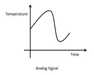
アナログ信号を処理する回路は、アナログ回路またはシステムと呼ばれます。アナログシステムの例を以下に示します。
- Filter
- Amplifiers
- テレビ受信機
- モータースピードコントローラー
アナログシステムのデメリット
- 精度が低い
- 汎用性が低い
- より多くのノイズ効果
- より多くの歪み
- 天候の影響が大きい
デジタル信号
A digital signalは、有限数の個別の値のみを持つ信号として定義されます。デジタル信号は連続信号ではありません。デジタル電子計算機では、入力はスイッチの助けを借りて与えられます。この入力は、2つの離散値またはレベルを持つ電気信号に変換されます。これらの1つは低レベルと呼ばれ、もう1つは高レベルと呼ばれます。信号は常に2つのレベルのいずれかになります。このタイプの信号はデジタル信号と呼ばれます。デジタル信号の例は次のとおりです。
- バイナリ信号
- オクタルシグナル
- 16進信号
デジタル信号のグラフィック表現(バイナリ)
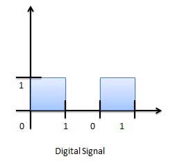
デジタル信号を処理する回路は、デジタルシステムまたはデジタル回路と呼ばれます。デジタルシステムの例は次のとおりです。
- Registers
- Flip-flop
- Counters
- Microprocessors
デジタルシステムの利点
- より正確に
- より多様性
- 歪みが少ない
- 簡単なコミュニケーション
- 情報の保存の可能性
アナログ信号とデジタル信号の比較
| SN | アナログ信号 | デジタル信号 |
|---|---|---|
| 1 | アナログ信号には無限の値があります。 | デジタル信号には有限の値があります。 |
| 2 | アナログ信号は連続的な性質を持っています。 | デジタル信号には離散的な性質があります。 |
| 3 | アナログ信号は、トランスデューサーと信号発生器によって生成されます。 | デジタル信号はA / Dコンバーターによって生成されます。 |
| 4 | アナログ信号の例-正弦波、三角波。 | デジタル信号の例-バイナリ信号。 |
デジタルシステムは、数字と呼ばれるいくつかの記号があり、これらの記号が数字の中で占める位置に応じて異なる値を表す場合にのみ、位置番号システムを理解できます。
数値の各桁の値は、次を使用して決定できます。
数字
数字の桁の位置
記数法の基数(基数は、記数法で使用可能な合計桁数として定義されます)。
10進法
私たちが日常生活で使用している記数法は、10進法です。10進数システムは、0から9までの10桁を使用するため、基数10になります。10進数システムでは、10進数の左側の連続する位置は、単位、数十、数百、数千などを表します。
各位置は、ベース(10)の特定のパワーを表します。たとえば、10進数1234は、単位の位置に4、10の位置に3、百の位置に2、千の位置に1の数字で構成され、その値は次のように記述できます。
(1×1000) + (2×100) + (3×10) + (4×l)
(1×10³) + (2×10²) + (3×101) + (4×l00)
1000 + 200 + 30 + 1
1234コンピュータープログラマーまたはIT専門家として、コンピューターで頻繁に使用される次の番号システムを理解する必要があります。
| SN | 記数法と説明 |
|---|---|
| 1 | Binary Number System 基数2。使用桁数:0、1 |
| 2 | Octal Number System 基数8。使用される数字:0から7 |
| 3 | Hexa Decimal Number System 基数16。使用される数字:0から9、使用される文字:A- F |
2進数システム
特徴
0と1の2桁を使用します。
2進数システムとも呼ばれます
2進数の各位置は、基数(2)の0乗を表します。例:2 0
2進数の最後の位置は、基数(2)のx乗を表します。例:2 xここで、xは最後の位置-1を表します。
例
2進数:10101 2
10進数の等価物の計算-
| ステップ | 2進数 | 10進数 |
|---|---|---|
| ステップ1 | 10101 2 | ((1×2 4)+(0×2 3)+(1×2 2)+(0×2 1)+(1×2 0))10 |
| ステップ2 | 10101 2 | (16 + 0 + 4 + 0 + 1)10 |
| ステップ3 | 10101 2 | 21 10 |
Note:10101 2は通常、10101と表記されます。
8進数システム
特徴
0、1、2、3、4、5、6、7の8桁を使用します。
基数8の記数法とも呼ばれます
8進数の各位置は、基数(8)の0乗を表します。例:8 0
8進数の最後の位置は、基数(8)のx乗を表します。例:8 xここで、xは最後の位置-1を表します。
例
進数- 12570 8
10進数の等価物の計算-
| ステップ | 8進数 | 10進数 |
|---|---|---|
| ステップ1 | 12570 8 | ((1×8 4)+(2×8 3)+(5×8 2)+(7×8 1)+(0×8 0))10 |
| ステップ2 | 12570 8 | (4096 + 1024 + 320 + 56 + 0)10 |
| ステップ3 | 12570 8 | 5496 10 |
Note:12570 8は通常、12570と表記されます。
16進数システム
特徴
10桁と6文字、0、1、2、3、4、5、6、7、8、9、A、B、C、D、E、Fを使用します。
文字は10から始まる数字を表します。A= 10、B = 11、C = 12、D = 13、E = 14、F = 15。
基数16の記数法とも呼ばれます。
16進数の各位置は、基数(16)の0乗を表します。実施例16 0。
16進数の最後の位置は、基数(16)のx乗を表します。例16xここで、xは最後の位置-1を表します。
例-
16進数:19FDE 16
10進数の等価物の計算-
| ステップ | 16進数 | 10進数 |
|---|---|---|
| ステップ1 | 19FDE 16 | ((1×16 4)+(9×16 3)+(F×16 2)+(D×16 1)+(E×16 0))10 |
| ステップ2 | 19FDE 16 | ((1×16 4)+(9×16 3)+(15×16 2)+(13×16 1)+(14×16 0))10 |
| ステップ3 | 19FDE 16 | (65536 + 36864 + 3840 + 208 + 14)10 |
| ステップ4 | 19FDE 16 | 106462 10 |
Note −19FDE 16は通常、19FDEと表記されます。
ある基数から別の基数に数値を変換するために使用できる方法や手法はたくさんあります。ここでは、次のことを示します。
- 他の基数システムへの10進数
- 10進数への他の基本システム
- 非10進数への他の基本システム
- ショートカット方式-バイナリからオクタル
- ショートカット方式-8進数から2進数
- ショートカットメソッド-バイナリから16進数
- ショートカット方式-16進数から2進数
他の基数システムへの10進数
ステップ
Step 1 −変換する10進数を新しい底の値で割ります。
Step 2 −ステップ1の余りを、新しい基数の右端の桁(最下位桁)として取得します。
Step 3 −前の除算の商を新しいベースで除算します。
Step 4 −ステップ3の余りを、新しいベース番号の次の桁(左側)として記録します。
ステップ3と4を繰り返し、ステップ3で商がゼロになるまで、余りを右から左に取得します。
このようにして得られた最後の余りは、新しいベース番号の最上位桁(MSD)になります。
例-
10進数:29 10
等価バイナリの計算-
| ステップ | 操作 | 結果 | 残り |
|---|---|---|---|
| ステップ1 | 29/2 | 14 | 1 |
| ステップ2 | 14/2 | 7 | 0 |
| ステップ3 | 7/2 | 3 | 1 |
| ステップ4 | 3/2 | 1 | 1 |
| ステップ5 | 1/2 | 0 | 1 |
手順2と4で説明したように、最初の剰余が最下位桁(LSD)になり、最後の剰余が最上位桁(MSD)になるように、剰余を逆の順序で配置する必要があります。
十進数- 29 10 =バイナリ数- 11101 2。
その他の基数から10進法
ステップ
Step 1 −各桁の列(位置)値を決定します(これは、桁の位置と記数法の基数によって異なります)。
Step 2 −(ステップ1で)取得した列の値に、対応する列の桁を掛けます。
Step 3 −手順2で計算した積を合計します。合計は10進数の同等の値です。
例
バイナリ番号- 11101 2
10進数の等価物の計算-
| ステップ | 2進数 | 10進数 |
|---|---|---|
| ステップ1 | 11101 2 | ((1×2 4)+(1×2 3)+(1×2 2)+(0×2 1)+(1×2 0))10 |
| ステップ2 | 11101 2 | (16 + 8 + 4 + 0 + 1)10 |
| ステップ3 | 11101 2 | 29 10 |
2進数− 11101 2 = 10進数− 29 10
その他の基本システムから非10進システム
ステップ
Step 1 −元の数値を10進数(基数10)に変換します。
Step 2 −取得した10進数を新しい基数に変換します。
例
8進数− 25 8
等価バイナリの計算-
ステップ1-10進数に変換
| ステップ | 8進数 | 10進数 |
|---|---|---|
| ステップ1 | 25 8 | ((2×8 1)+(5×8 0))10 |
| ステップ2 | 25 8 | (16 + 5)10 |
| ステップ3 | 25 8 | 21 10 |
8進数− 25 8 = 10進数− 21 10
ステップ2-10進数を2進数に変換する
| ステップ | 操作 | 結果 | 残り |
|---|---|---|---|
| ステップ1 | 21/2 | 10 | 1 |
| ステップ2 | 10/2 | 5 | 0 |
| ステップ3 | 5/2 | 2 | 1 |
| ステップ4 | 2/2 | 1 | 0 |
| ステップ5 | 1/2 | 0 | 1 |
10進数− 21 10 = 2進数− 10101 2
8進数− 25 8 = 2進数− 10101 2
ショートカット方式-2進数から8進数
ステップ
Step 1 − 2進数を3つのグループに分割します(右から開始)。
Step 2 −3つの2進数の各グループを1つの8進数に変換します。
例
バイナリ番号- 10101 2
8進数の等価物の計算-
| ステップ | 2進数 | 8進数 |
|---|---|---|
| ステップ1 | 10101 2 | 010 101 |
| ステップ2 | 10101 2 | 2 8 5 8 |
| ステップ3 | 10101 2 | 25 8 |
2進数− 10101 2 = 8進数− 25 8
ショートカット方式-オクタルからバイナリ
ステップ
Step 1 −各8進数を3桁の2進数に変換します(この変換では、8進数は10進数として扱われる場合があります)。
Step 2 −結果のすべての2進数グループ(それぞれ3桁)を1つの2進数に結合します。
例
8進数− 25 8
等価バイナリの計算-
| ステップ | 8進数 | 2進数 |
|---|---|---|
| ステップ1 | 25 8 | 2 10 5 10 |
| ステップ2 | 25 8 | 010 2 101 2 |
| ステップ3 | 25 8 | 010101 2 |
8進数− 25 8 = 2進数− 10101 2
ショートカットメソッド-バイナリから16進数
ステップ
Step 1 − 2進数を4つのグループに分割します(右から開始)。
Step 2 −4桁の2進数の各グループを1つの16進記号に変換します。
例
バイナリ番号- 10101 2
16進数の等価物の計算-
| ステップ | 2進数 | 16進数 |
|---|---|---|
| ステップ1 | 10101 2 | 0001 0101 |
| ステップ2 | 10101 2 | 1 10 5 10 |
| ステップ3 | 10101 2 | 15 16 |
2進数− 10101 2 = 16進数− 15 16
ショートカットメソッド-16進数から2進数
ステップ
Step 1 −各16進数を4桁の2進数に変換します(この変換では、16進数は10進数として扱われる場合があります)。
Step 2 −結果のすべての2進数グループ(それぞれ4桁)を1つの2進数に結合します。
例
進数- 15 16
等価バイナリの計算-
| ステップ | 16進数 | 2進数 |
|---|---|---|
| ステップ1 | 15 16 | 1 10 5 10 |
| ステップ2 | 15 16 | 0001 2 0101 2 |
| ステップ3 | 15 16 | 00010101 2 |
16進数− 15 16 = 2進数− 10101 2
コーディングにおいて、数字、文字、または単語が特定の記号のグループによって表される場合、数字、文字、または単語がエンコードされていると言われます。シンボルのグループはコードと呼ばれます。デジタルデータは、バイナリビットのグループとして表され、保存され、送信されます。このグループは、binary code。バイナリコードは、数字と英数字で表されます。
バイナリコードの利点
以下は、バイナリコードが提供する利点のリストです。
バイナリコードは、コンピュータアプリケーションに適しています。
バイナリコードはデジタル通信に適しています。
バイナリコードを使用する場合、バイナリコードはデジタル回路の分析と設計を行います。
0と1のみを使用しているため、実装が容易になります。
バイナリコードの分類
コードは大きく次の4つのカテゴリに分類されます。
- 加重コード
- 重み付けされていないコード
- 2進化10進コード
- 英数字コード
- コードの検出エラー
- エラー訂正コード
加重コード
加重バイナリコードは、位置加重の原則に従うバイナリコードです。数字の各位置は特定の重量を表します。コードのいくつかのシステムは、10進数の0から9を表すために使用されます。これらのコードでは、各10進数は4ビットのグループで表されます。
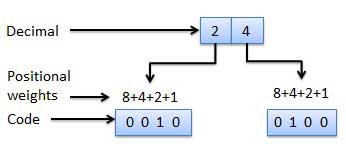
重み付けされていないコード
このタイプのバイナリコードでは、位置の重みは割り当てられません。重み付けされていないコードの例は、Excess-3コードとグレイコードです。
過剰-3コード
Excess-3コードはXS-3コードとも呼ばれます。これは、10進数を表すために使用される重み付けされていないコードです。Excess-3コードワードは、8421の各コードワードに(0011)2または(3)10を追加した8421BCDコードワードから派生します。Excess-3コードは次のように取得されます。

例
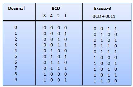
グレイコード
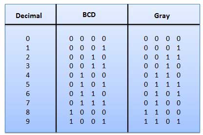
これは重み付けされていないコードであり、算術コードではありません。つまり、ビット位置に特定の重みが割り当てられていません。これは非常に特別な機能を備えており、図1に示すように、10進数がインクリメントされるたびに1ビットだけが変更されます。一度に1ビットしか変化しないため、グレイコードは単位距離コードと呼ばれます。グレイコードは巡回符号です。グレイコードは算術演算には使用できません。
グレイコードの適用
グレイコードは、シャフト位置エンコーダで一般的に使用されています。
シャフト位置エンコーダは、シャフトの角度位置を表すコードワードを生成します。
二進化十進表現(BCD)コード
このコードでは、各10進数は4ビットの2進数で表されます。BCDは、各10進数を2進コードで表現する方法です。BCDでは、4ビットで16個の数値(0000から1111)を表すことができます。ただし、BCDコードでは、これらの最初の10個(0000から1001)のみが使用されます。残りの6つのコードの組み合わせ、つまり1010から1111は、BCDでは無効です。

BCDコードの利点
- これは、10進法と非常によく似ています。
- 10進数の0から9に相当する2進数のみを覚えておく必要があります。
BCDコードのデメリット
BCDの加算と減算には異なる規則があります。
BCD演算はもう少し複雑です。
BCDは、10進数を表すために、2進数よりも多くのビット数を必要とします。したがって、BCDはバイナリよりも効率が低くなります。
英数字コード
2桁またはビットは、「0」または「1」の2つの状態しかないため、2つのシンボルのみを表すことができます。しかし、通信にはさらに多くの記号が必要なため、これは2台のコンピューター間の通信には十分ではありません。これらの記号は、大文字と小文字、0から9までの数字、句読点、その他の記号で26個のアルファベットを表すために必要です。
英数字コードは、数字と英字を表すコードです。ほとんどの場合、このようなコードは、情報を伝達するために必要な記号やさまざまな指示などの他の文字も表します。英数字コードは、少なくとも10桁と26文字のアルファベット、つまり合計36項目を表す必要があります。次の3つの英数字コードは、データ表現に非常に一般的に使用されます。
- 情報交換のためのアメリカ標準コード(ASCII)。
- 拡張バイナリコード化10進交換コード(EBCDIC)。
- 5ビットのBaudotコード。
ASCIIコードは7ビットコードですが、EBCDICは8ビットコードです。ASCIIコードは世界中でより一般的に使用されていますが、EBCDICは主に大型のIBMコンピューターで使用されています。
エラーコード
データ送信中にデータを検出して修正するために利用できるバイナリコード技術があります。
| エラーコード | 説明 |
|---|---|
エラーの検出と訂正 |
エラー検出および訂正コード技術 |
コードをある形式から別の形式に変換するために使用できる方法や手法はたくさんあります。ここでは、次のことを示します
- バイナリからBCDへの変換
- BCDからバイナリへの変換
- BCDからExcess-3へ
- BCDへのExcess-3
バイナリからBCDへの変換
ステップ
Step 1 --2進数を10進数に変換します。
Step 2 -10進数をBCDに変換します。
例-(11101)2をBCDに変換します。
ステップ1-10進数に変換
バイナリ番号- 11101 2
10進数の等価物の計算-
| ステップ | 2進数 | 10進数 |
|---|---|---|
| ステップ1 | 11101 2 | ((1×2 4)+(1×2 3)+(1×2 2)+(0×2 1)+(1×2 0))10 |
| ステップ2 | 11101 2 | (16 + 8 + 4 + 0 + 1)10 |
| ステップ3 | 11101 2 | 29 10 |
2進数− 11101 2 = 10進数− 29 10
ステップ2-BCDに変換する
10進数− 29 10
BCD相当の計算。各桁を、同等の4桁の2進数のグループに変換します。
| ステップ | 10進数 | 変換 |
|---|---|---|
| ステップ1 | 29 10 | 0010 2 1001 2 |
| ステップ2 | 29 10 | 00101001 BCD |
結果
(11101)2 = (00101001)BCDBCDからバイナリへの変換
ステップ
Step 1 --BCD番号を10進数に変換します。
Step 2 -10進数を2進数に変換します。
例-(00101001)BCDをバイナリに変換します。
ステップ1-BCDに変換する
BCD番号-(00101001)BCD
10進数の等価物を計算します。各4桁をグループに変換し、各グループに相当する10進数を取得します。
| ステップ | BCD番号 | 変換 |
|---|---|---|
| ステップ1 | (00101001)BCD | 0010 2 1001 2 |
| ステップ2 | (00101001)BCD | 2 10 9 10 |
| ステップ3 | (00101001)BCD | 29 10 |
BCD番号-(00101001)BCD = 10進数-29 10
ステップ2-バイナリに変換する
10進数から2進数への変換に長除算法を使用しました。
10進数− 29 10
等価バイナリの計算-
| ステップ | 操作 | 結果 | 残り |
|---|---|---|---|
| ステップ1 | 29/2 | 14 | 1 |
| ステップ2 | 14/2 | 7 | 0 |
| ステップ3 | 7/2 | 3 | 1 |
| ステップ4 | 3/2 | 1 | 1 |
| ステップ5 | 1/2 | 0 | 1 |
手順2と4で説明したように、最初の剰余が最下位桁(LSD)になり、最後の剰余が最上位桁(MSD)になるように、剰余を逆の順序で配置する必要があります。
10進数− 29 10 = 2進数− 11101 2
結果
(00101001)BCD = (11101)2BCDからExcess-3へ
ステップ
Step 1 --BCDを10進数に変換します。
Step 2-この10進数に(3)10を追加します。
Step 3 -バイナリに変換してexcess-3コードを取得します。
例-(0110)BCDをExcess-3に変換します。
ステップ1-10進数に変換
(0110)BCD = 6 10
ステップ2-小数に3を追加
(6)10 +(3)10 =(9)10
ステップ3-Excess-3に変換する
(9)10 =(1001)2
結果
(0110)BCD = (1001)XS-3Excess-3からBCDへの変換
ステップ
Step 1-対応するBCDコードを取得するために、超過3桁の各4ビットから(0011)2を減算します。
例-(10011010)XS-3をBCDに変換します。
Given XS-3 number  = 1 0 0 1 1 0 1 0
Subtract (0011)2   = 1 0 0 1 0 1 1 1
                    --------------------
               BCD = 0 1 1 0   0 1 1 1
結果
(10011010)XS-3 = (01100111)BCD減算操作を簡素化するため、および論理操作のために、補数がデジタルコンピュータで使用されます。各基数-rシステム(基数rは記数法の底を表す)には、2種類の補数があります。
| SN | 補体 | 説明 |
|---|---|---|
| 1 | 基数補数 | 基数の補集合はrの補集合と呼ばれます |
| 2 | 基数の補数の減少 | 減少した基数の補数は、(r-1)の補数と呼ばれます |
バイナリシステムは補完します
バイナリシステムの基数はr = 2であるため、バイナリシステムの2種類の補数は、2の補数と1の補数です。
1の補数
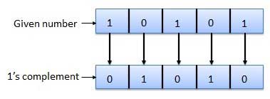
数値の1の補数は、すべて1を0に、すべて0を1に変更することによって検出されます。これは、補数または1の補数を取ると呼ばれます。1の補数の例は次のとおりです。
2の補数
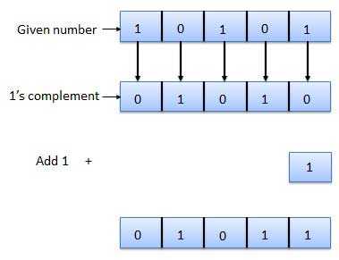
2の2の補数は、1の補数の最下位ビット(LSB)に1を加算することによって取得されます。
2の補数= 1の補数+1
2の補数の例は次のとおりです。
バイナリ演算は、すべてのデジタルコンピュータおよび他の多くのデジタルシステムの重要な部分です。
バイナリ加算
これは、2進数の減算、乗算、除算の鍵です。バイナリ加算には4つのルールがあります。
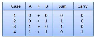
4番目のケースでは、2進加算により、(1 + 1 = 10)の合計が作成されます。つまり、指定された列に0が書き込まれ、次の列に1が繰り越されます。
例-加算

バイナリ減算
Subtraction and Borrow、これらの2つの単語は、バイナリ減算に非常に頻繁に使用されます。バイナリ減算には4つのルールがあります。
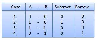
例-減算

バイナリ乗算
2進乗算は、10進乗算に似ています。0と1のみが含まれるため、10進数の乗算よりも簡単です。バイナリ乗算には4つのルールがあります。
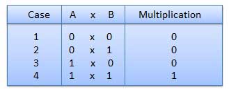
例-乗算
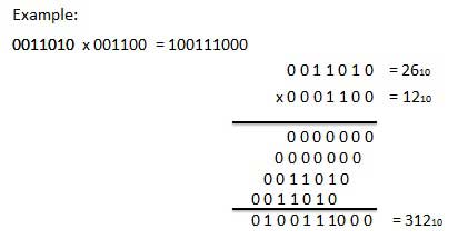
バイナリ除算
2進数の除算は、10進数の除算に似ています。筆算手続きと呼ばれます。
例-除算

8進数システム
以下は、8進数システムの特徴です。
0、1、2、3、4、5、6、7の8桁を使用します。
基数8の記数法とも呼ばれます。
8進数の各位置は、基数(8)の0乗を表します。例:8 0
8進数の最後の位置は、基数(8)のx乗を表します。例:8 xここで、xは最後の位置-1を表します。
例
進数- 12570 8
10進数の等価物の計算-
| ステップ | 8進数 | 10進数 |
|---|---|---|
| ステップ1 | 12570 8 | ((1×8 4)+(2×8 3)+(5×8 2)+(7×8 1)+(0×8 0))10 |
| ステップ2 | 12570 8 | (4096 + 1024 + 320 + 56 + 0)10 |
| ステップ3 | 12570 8 | 5496 10 |
Note −12570 8は通常、12570と表記されます。
8進数の加算
次の8進数加算表は、8進数加算を処理するのに役立ちます。
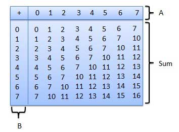
このテーブルを使用するには、この例で使用される指示に従ってください:6追加8と5 8。A列で6を見つけ、次にB列で5を見つけます。これらの2つの列が交差する「合計」領域のポイントは、2つの数値の「合計」です。
68 + 58 = 138.例-加算

8進数の減算
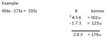
8進数の減算は、他の記数法の数値の減算と同じ規則に従います。唯一のバリエーションは借りた数です。小数のシステムでは、10のグループ借りる10。バイナリシステムでは、2のグループ借りる10。進システムでは、8のグループ借りる10。
例-減算
16進数システム
以下は、16進数システムの特徴です。
10桁と6文字、0、1、2、3、4、5、6、7、8、9、A、B、C、D、E、Fを使用します。
文字は10から始まる数字を表します。A= 10、B = 11、C = 12、D = 13、E = 14、F = 15。
基数16の記数法とも呼ばれます。
16進数の各位置は、基数(16)の0乗を表します。例− 16 0
16進数の最後の位置は、基数(16)のx乗を表します。例-16xここで、xは最後の位置-1を表します。
例
16進数− 19FDE 16
10進数の等価物の計算-
| ステップ | 16進数 | 10進数 |
|---|---|---|
| ステップ1 | 19FDE 16 | ((1×16 4)+(9×16 3)+(F×16 2)+(D×16 1)+(E×16 0))10 |
| ステップ2 | 19FDE 16 | ((1×16 4)+(9×16 3)+(15×16 2)+(13×16 1)+(14×16 0))10 |
| ステップ3 | 19FDE 16 | (65536 + 36864 + 3840 + 208 + 14)10 |
| ステップ4 | 19FDE 16 | 106462 10 |
Note −19FDE 16は通常、19FDEと表記されます。
16進数の加算
次の16進加算表は、16進加算を処理するのに大いに役立ちます。
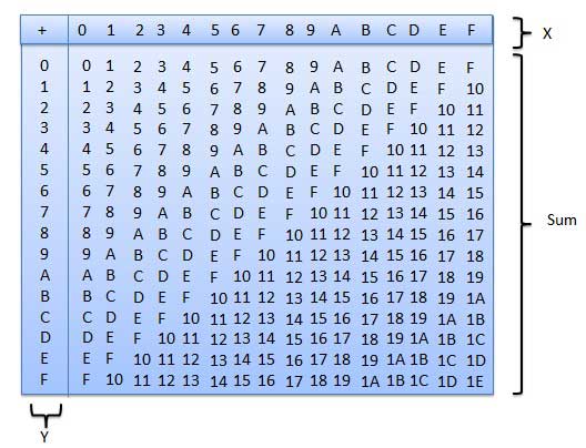
このテーブルを使用するには、この例で使用される指示に従ってください-追加16 5 16。X列でAを見つけ、次にY列で5を見つけます。これらの2つの列が交差する「合計」領域のポイントは、2つの数値の合計です。
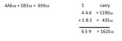
A16 + 516 = F16.例-加算
16進減算
16進数の減算は、他の記数法の数値の減算と同じ規則に従います。唯一のバリエーションは借りた数です。小数のシステムでは、10のグループ借りる10。バイナリシステムでは、2のグループ借りる10。進システムでは、16のグループ借りる10。
例-減算

ブール代数は、デジタル(論理)回路を分析および簡略化するために使用されます。0と1の2進数のみを使用します。Binary Algebra または logical Algebra。ブール代数はによって発明されましたGeorge Boole 1854年。
ブール代数のルール
以下は、ブール代数で使用される重要なルールです。
使用される変数は2つの値のみを持つことができます。HIGHの場合はバイナリ1、LOWの場合はバイナリ0。
変数の補集合は、オーバーバー(-)で表されます。したがって、変数Bの補集合はとして表され
ます。したがって、B = 0の場合は = 1、B = 1の場合は
 = 0です。
変数のOR処理は、変数間のプラス(+)記号で表されます。たとえば、A、B、CのORリングは、A + B + Cとして表されます。
2つ以上の変数の論理ANDは、ABCのようにそれらの間にドットを書き込むことによって表されます。ABCのようにドットが省略される場合があります。
ブール法
ブール法には6つのタイプがあります。
可換法則
次の式を満たす二項演算は、可換演算と呼ばれます。

可換法則によれば、変数の順序を変更しても、論理回路の出力には何の影響もありません。
結合法則
この法則は、論理演算が実行される順序は、その効果が同じであるため、無関係であると述べています。

分配法則
分配法則は次の条件を述べています。

AND法
これらの法則はAND演算を使用します。したがって、それらは次のように呼ばれますAND 法律。

または法律
これらの法律はOR演算を使用しています。したがって、それらは次のように呼ばれますOR 法律。

反転法
この法則はNOT演算を使用します。反転法則では、変数を2回反転すると、元の変数自体が生成されるとされています。

重要なブール定理
以下は、いくつかの重要なブール定理です。
| ブール関数/定理 | 説明 |
|---|---|
ブール関数 |
ブール関数と式、KマップとNANDゲートの実現 |
ド・モルガンの定理 |
ド・モルガンの定理1と定理2 |
論理ゲートは、あらゆるデジタルシステムの基本的な構成要素です。これは、1つまたは複数の入力と1つの出力のみを備えた電子回路です。入力と出力の関係は、certain logic。これに基づいて、論理ゲートはANDゲート、ORゲート、NOTゲートなどの名前が付けられます。
ANDゲート
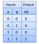
AND演算を実行する回路を図に示します。n個の入力(n> = 2)と1個の出力があります。

論理図

真理値表
またはゲート
OR演算を実行する回路を図に示します。n個の入力(n> = 2)と1個の出力があります。

論理図

真理値表
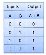
ゲートではありません
NOTゲートは別名 Inverter。1つの入力Aと1つの出力Yがあります。

論理図

真理値表
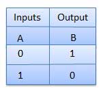
NANDゲート
NOT-AND演算はNAND演算として知られています。n個の入力(n> = 2)と1個の出力があります。

論理図

真理値表
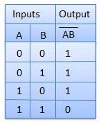
NORゲート
NOT-OR演算は、NOR演算と呼ばれます。n個の入力(n> = 2)と1個の出力があります。

論理図

真理値表
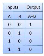
XORゲート
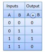
XOR or Ex-OR gate is a special type of gate. It can be used in the half adder, full adder and subtractor. The exclusive-OR gate is abbreviated as EX-OR gate or sometime as X-OR gate. It has n input (n >= 2) and one output.

Logic diagram

Truth Table
XNOR Gate
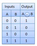
XNOR gate is a special type of gate. It can be used in the half adder, full adder and subtractor. The exclusive-NOR gate is abbreviated as EX-NOR gate or sometime as X-NOR gate. It has n input (n >= 2) and one output.

Logic diagram

Truth Table
Combinational circuit is a circuit in which we combine the different gates in the circuit, for example encoder, decoder, multiplexer and demultiplexer. Some of the characteristics of combinational circuits are following −
The output of combinational circuit at any instant of time, depends only on the levels present at input terminals.
The combinational circuit do not use any memory. The previous state of input does not have any effect on the present state of the circuit.
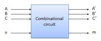
A combinational circuit can have an n number of inputs and m number of outputs.
Block diagram
We're going to elaborate few important combinational circuits as follows.
Half Adder
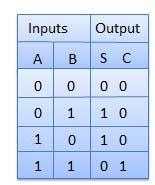
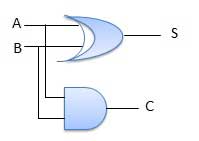
Half adder is a combinational logic circuit with two inputs and two outputs. The half adder circuit is designed to add two single bit binary number A and B. It is the basic building block for addition of two single bit numbers. This circuit has two outputs carry and sum.
Block diagram

Truth Table
Circuit Diagram
Full Adder
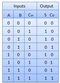
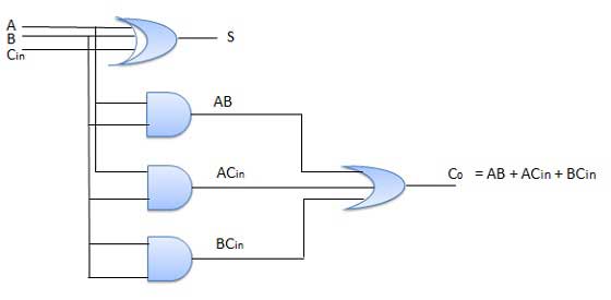
Full adder is developed to overcome the drawback of Half Adder circuit. It can add two one-bit numbers A and B, and carry c. The full adder is a three input and two output combinational circuit.
Block diagram

Truth Table
Circuit Diagram
N-Bit Parallel Adder
The Full Adder is capable of adding only two single digit binary number along with a carry input. But in practical we need to add binary numbers which are much longer than just one bit. To add two n-bit binary numbers we need to use the n-bit parallel adder. It uses a number of full adders in cascade. The carry output of the previous full adder is connected to carry input of the next full adder.
4 Bit Parallel Adder
In the block diagram, A0 and B0 represent the LSB of the four bit words A and B. Hence Full Adder-0 is the lowest stage. Hence its Cin has been permanently made 0. The rest of the connections are exactly same as those of n-bit parallel adder is shown in fig. The four bit parallel adder is a very common logic circuit.
Block diagram

N-Bit Parallel Subtractor
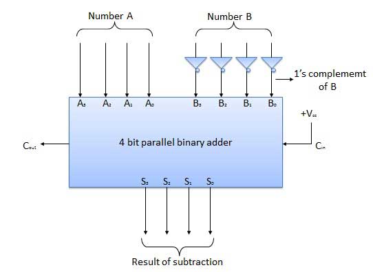
The subtraction can be carried out by taking the 1's or 2's complement of the number to be subtracted. For example we can perform the subtraction (A-B) by adding either 1's or 2's complement of B to A. That means we can use a binary adder to perform the binary subtraction.
4 Bit Parallel Subtractor
The number to be subtracted (B) is first passed through inverters to obtain its 1's complement. The 4-bit adder then adds A and 2's complement of B to produce the subtraction. S3 S2 S1 S0 represents the result of binary subtraction (A-B) and carry output Cout represents the polarity of the result. If A > B then Cout = 0 and the result of binary form (A-B) then Cout = 1 and the result is in the 2's complement form.
Block diagram
Half Subtractors
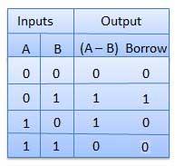
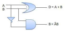
Half subtractor is a combination circuit with two inputs and two outputs (difference and borrow). It produces the difference between the two binary bits at the input and also produces an output (Borrow) to indicate if a 1 has been borrowed. In the subtraction (A-B), A is called as Minuend bit and B is called as Subtrahend bit.
Truth Table
Circuit Diagram
Full Subtractors
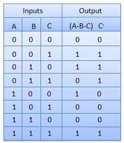
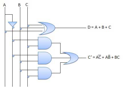
The disadvantage of a half subtractor is overcome by full subtractor. The full subtractor is a combinational circuit with three inputs A,B,C and two output D and C'. A is the 'minuend', B is 'subtrahend', C is the 'borrow' produced by the previous stage, D is the difference output and C' is the borrow output.
Truth Table
Circuit Diagram
Multiplexers
Multiplexer is a special type of combinational circuit. There are n-data inputs, one output and m select inputs with 2m = n. It is a digital circuit which selects one of the n data inputs and routes it to the output. The selection of one of the n inputs is done by the selected inputs. Depending on the digital code applied at the selected inputs, one out of n data sources is selected and transmitted to the single output Y. E is called the strobe or enable input which is useful for the cascading. It is generally an active low terminal that means it will perform the required operation when it is low.
Block diagram
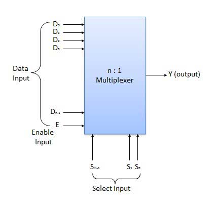
Multiplexers come in multiple variations
- 2 : 1 multiplexer
- 4 : 1 multiplexer
- 16 : 1 multiplexer
- 32 : 1 multiplexer
Block Diagram
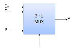
Truth Table
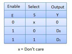
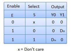
Demultiplexers
A demultiplexer performs the reverse operation of a multiplexer i.e. it receives one input and distributes it over several outputs. It has only one input, n outputs, m select input. At a time only one output line is selected by the select lines and the input is transmitted to the selected output line. A de-multiplexer is equivalent to a single pole multiple way switch as shown in fig.
Demultiplexers comes in multiple variations.
- 1 : 2 demultiplexer
- 1 : 4 demultiplexer
- 1 : 16 demultiplexer
- 1 : 32 demultiplexer
Block diagram
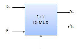
Truth Table
Decoder
A decoder is a combinational circuit. It has n input and to a maximum m = 2n outputs. Decoder is identical to a demultiplexer without any data input. It performs operations which are exactly opposite to those of an encoder.
Block diagram

Examples of Decoders are following.
- Code converters
- BCD to seven segment decoders
- Nixie tube decoders
- Relay actuator
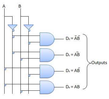
2 to 4 Line Decoder
The block diagram of 2 to 4 line decoder is shown in the fig. A and B are the two inputs where D through D are the four outputs. Truth table explains the operations of a decoder. It shows that each output is 1 for only a specific combination of inputs.
Block diagram

Truth Table

Logic Circuit
Encoder
Encoder is a combinational circuit which is designed to perform the inverse operation of the decoder. An encoder has n number of input lines and m number of output lines. An encoder produces an m bit binary code corresponding to the digital input number. The encoder accepts an n input digital word and converts it into an m bit another digital word.
Block diagram

Examples of Encoders are following.
- Priority encoders
- Decimal to BCD encoder
- Octal to binary encoder
- Hexadecimal to binary encoder
Priority Encoder
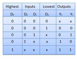
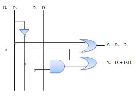
This is a special type of encoder. Priority is given to the input lines. If two or more input line are 1 at the same time, then the input line with highest priority will be considered. There are four input D0, D1, D2, D3 and two output Y0, Y1. Out of the four input D3 has the highest priority and D0 has the lowest priority. That means if D3 = 1 then Y1 Y1 = 11 irrespective of the other inputs. Similarly if D3 = 0 and D2 = 1 then Y1 Y0 = 10 irrespective of the other inputs.
Block diagram

Truth Table
Logic Circuit
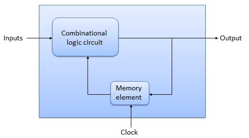
The combinational circuit does not use any memory. Hence the previous state of input does not have any effect on the present state of the circuit. But sequential circuit has memory so output can vary based on input. This type of circuits uses previous input, output, clock and a memory element.
Block diagram
Flip Flop
Flip flop is a sequential circuit which generally samples its inputs and changes its outputs only at particular instants of time and not continuously. Flip flop is said to be edge sensitive or edge triggered rather than being level triggered like latches.
S-R Flip Flop
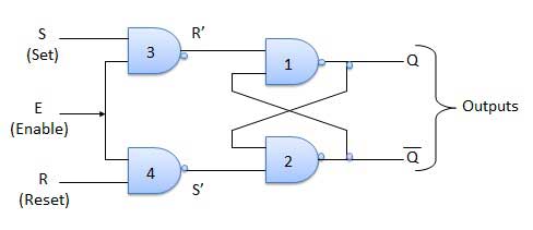
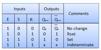
It is basically S-R latch using NAND gates with an additional enable input. It is also called as level triggered SR-FF. For this, circuit in output will take place if and only if the enable input (E) is made active. In short this circuit will operate as an S-R latch if E = 1 but there is no change in the output if E = 0.
Block Diagram

Circuit Diagram
Truth Table
Operation
| S.N. | Condition | Operation |
|---|---|---|
| 1 | S = R = 0 : No change | If S = R = 0 then output of NAND gates 3 and 4 are forced to become 1. Hence R' and S' both will be equal to 1. Since S' and R' are the input of the basic S-R latch using NAND gates, there will be no change in the state of outputs. |
| 2 | S = 0, R = 1, E = 1 | Since S = 0, output of NAND-3 i.e. R' = 1 and E = 1 the output of NAND-4 i.e. S' = 0. Hence Qn+1 = 0 and Qn+1 bar = 1. This is reset condition. |
| 3 | S = 1, R = 0, E = 1 | Output of NAND-3 i.e. R' = 0 and output of NAND-4 i.e. S' = 1. Hence output of S-R NAND latch is Qn+1 = 1 and Qn+1 bar = 0. This is the reset condition. |
| 4 | S = 1, R = 1, E = 1 | As S = 1, R = 1 and E = 1, the output of NAND gates 3 and 4 both are 0 i.e. S' = R' = 0. Hence the Race condition will occur in the basic NAND latch. |
Master Slave JK Flip Flop
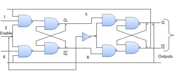
Master slave JK FF is a cascade of two S-R FF with feedback from the output of second to input of first. Master is a positive level triggered. But due to the presence of the inverter in the clock line, the slave will respond to the negative level. Hence when the clock = 1 (positive level) the master is active and the slave is inactive. Whereas when clock = 0 (low level) the slave is active and master is inactive.
Circuit Diagram
Truth Table
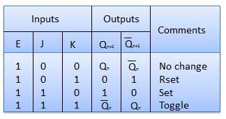
Operation
| S.N. | Condition | Operation |
|---|---|---|
| 1 | J = K = 0 (No change) | When clock = 0, the slave becomes active and master is inactive. But since the S and R inputs have not changed, the slave outputs will also remain unchanged. Therefore outputs will not change if J = K =0. |
| 2 | J = 0 and K = 1 (Reset) | Clock = 1 − Master active, slave inactive. Therefore outputs of the master become Q1 = 0 and Q1 bar = 1. That means S = 0 and R =1. Clock = 0 − Slave active, master inactive. Therefore outputs of the slave become Q = 0 and Q bar = 1. Again clock = 1 − Master active, slave inactive. Therefore even with the changed outputs Q = 0 and Q bar = 1 fed back to master, its output will be Q1 = 0 and Q1 bar = 1. That means S = 0 and R = 1. Hence with clock = 0 and slave becoming active the outputs of slave will remain Q = 0 and Q bar = 1. Thus we get a stable output from the Master slave. |
| 3 | J = 1 and K = 0 (Set) | Clock = 1 − Master active, slave inactive. Therefore outputs of the master become Q1 = 1 and Q1 bar = 0. That means S = 1 and R =0. Clock = 0 − Slave active, master inactive. Therefore outputs of the slave become Q = 1 and Q bar = 0. Again clock = 1 − then it can be shown that the outputs of the slave are stabilized to Q = 1 and Q bar = 0. |
| 4 | J = K = 1 (Toggle) | Clock = 1 − Master active, slave inactive. Outputs of master will toggle. So S and R also will be inverted. Clock = 0 − Slave active, master inactive. Outputs of slave will toggle. These changed output are returned back to the master inputs. But since clock = 0, the master is still inactive. So it does not respond to these changed outputs. This avoids the multiple toggling which leads to the race around condition. The master slave flip flop will avoid the race around condition. |
Delay Flip Flop / D Flip Flop
Delay Flip Flop or D Flip Flop is the simple gated S-R latch with a NAND inverter connected between S and R inputs. It has only one input. The input data is appearing at the output after some time. Due to this data delay between i/p and o/p, it is called delay flip flop. S and R will be the complements of each other due to NAND inverter. Hence S = R = 0 or S = R = 1, these input condition will never appear. This problem is avoid by SR = 00 and SR = 1 conditions.
Block Diagram

Circuit Diagram
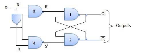
Truth Table
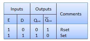
Operation
| S.N. | Condition | Operation |
|---|---|---|
| 1 | E = 0 | Latch is disabled. Hence no change in output. |
| 2 | E = 1 and D = 0 | If E = 1 and D = 0 then S = 0 and R = 1. Hence irrespective of the present state, the next state is Qn+1 = 0 and Qn+1 bar = 1. This is the reset condition. |
| 3 | E = 1 and D = 1 | If E = 1 and D = 1, then S = 1 and R = 0. This will set the latch and Qn+1 = 1 and Qn+1 bar = 0 irrespective of the present state. |
Toggle Flip Flop / T Flip Flop
Toggle flip flop is basically a JK flip flop with J and K terminals permanently connected together. It has only input denoted by T as shown in the Symbol Diagram. The symbol for positive edge triggered T flip flop is shown in the Block Diagram.
Symbol Diagram

Block Diagram

Truth Table
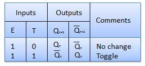
Operation
| S.N. | Condition | Operation |
|---|---|---|
| 1 | T = 0, J = K = 0 | The output Q and Q bar won't change |
| 2 | T = 1, J = K = 1 | Output will toggle corresponding to every leading edge of clock signal. |
Flip-flop is a 1 bit memory cell which can be used for storing the digital data. To increase the storage capacity in terms of number of bits, we have to use a group of flip-flop. Such a group of flip-flop is known as a Register. The n-bit register will consist of n number of flip-flop and it is capable of storing an n-bit word.
The binary data in a register can be moved within the register from one flip-flop to another. The registers that allow such data transfers are called as shift registers. There are four mode of operations of a shift register.
- シリアル入力シリアル出力
- シリアル入力パラレル出力
- パラレル入力シリアル出力
- パラレル入力パラレル出力
シリアル入力シリアル出力
すべてのフリップフロップを最初はリセット状態、つまりQ 3 = Q 2 = Q 1 = Q 0 = 0とします。4ビットの2進数11 1 1をレジスタに入力する場合、この数値は次のようになります。に適用されますDinLSBビットが最初に適用されたビット。FF-3、すなわちDのD入力3は、シリアルデータ入力に接続されています。Din。FF-3、すなわちQの出力3は、すなわちD次のフリップフロップの入力に接続されている2とになります。
ブロック図

操作
クロック信号を印加する前に、Q 3 Q 2 Q 1 Q 0 = 0000とし、入力する数値のLSBビットをDに印加します。したがって、D in = D 3 = 1です。クロックを適用します。クロックの最初の立ち下がりエッジでFF-3が設定され、レジスタに格納されているワードはQ 3 Q 2 Q 1 Q 0 = 1000です。

次のビットをのDに適用します。したがって、D in = 1です。クロックの次の負のエッジがヒットするとすぐに、FF-2が設定され、格納されているワードがQ 3 Q 2 Q 1 Q 0 = 1100に変更されます。

保存する次のビット、つまり1からDを適用します。クロックパルスを適用します。3番目の負のクロックエッジがヒットするとすぐに、FF-1が設定され、出力がQ 3 Q 2 Q 1 Q 0 = 1110に変更されます。

同様に、D in = 1で、4番目の負のクロックエッジが到着すると、レジスタに格納されるワードはQ 3 Q 2 Q 1 Q 0 = 1111です。

真理値表
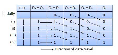
波形

シリアル入力パラレル出力
このようなタイプの操作では、データはシリアルに入力され、並列に取り出されます。
データは少しずつロードされます。データがロードされている限り、出力は無効になります。
データのロードが完了するとすぐに、すべてのフリップフロップに必要なデータが含まれ、出力が有効になり、ロードされたすべてのデータがすべての出力ラインで同時に使用できるようになります。
4ビットワードをロードするには、4クロックサイクルが必要です。したがって、SIPOモードの動作速度はSISOモードの動作速度と同じです。
ブロック図
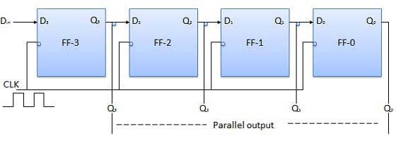
パラレル入力シリアル出力(PISO)
データビットは並列に入力されます。
以下に示す回路は、4ビットのパラレル入力シリアル出力レジスタです。
前のフリップフロップの出力は、組み合わせ回路を介して次のフリップフロップの入力に接続されます。
バイナリ入力ワードB0、B 1、B 2、B 3は、同じ組み合わせ回路を介して適用されます。
この回路が機能できるモードには、シフトモードとロードモードの2つがあります。
ロードモード
シフト/ロードバーライン(0)が低い場合には、ANDゲート2、4及びそれらがB通過するアクティブになっ6 1、B 2、B 3ビットには、対応するフリップフロップ。クロックの低い立ち上がりエッジ、バイナリ入力Bに0、B 1、B 2、B 3は対応するにロードされますフリップフロップ。したがって、並列ロードが行われます。
シフトモード
シフト/ロードバーラインが低い場合(1)、ANDゲート2、4、および6は非アクティブになります。したがって、データの並列ロードは不可能になります。ただし、ANDゲート1、3、および5がアクティブになります。したがって、クロックパルスの適用時にデータをビットごとに左から右にシフトします。したがって、パラレルインシリアルアウト操作が行われます。
ブロック図
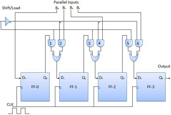
パラレル入力パラレル出力(PIPO)
このモードでは、図4は、バイナリ入力ビットb 0、B 1、B 2はB、3はデータ入力に印加されるD 0、D 1、D 2、D 3はそれぞれ4個のフリップフロップのを。負のクロックエッジが適用されるとすぐに、入力バイナリビットがフリップフロップに同時にロードされます。ロードされたビットは、出力側に同時に表示されます。すべてのビットをロードするには、クロックパルスのみが不可欠です。
ブロック図
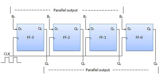
双方向シフトレジスタ
2進数を左に1桁シフトすると、元の数値に2を掛けることになります。同様に、2進数を右に1桁シフトすると、元の数値を2で割ることになります。
したがって、シフトレジスタを使用して、指定された2進数を乗算および除算する場合は、データを左方向または右方向に移動できるはずです。
このようなレジスタは双方向レジスタと呼ばれます。4ビットの双方向シフトレジスタを図1に示します。
シリアル右シフトデータ入力DRとシリアル左シフトデータ入力DLの2つのシリアル入力と、モード選択入力(M)があります。
ブロック図
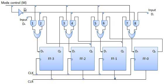
操作
| SN | 状態 | 操作 |
|---|---|---|
| 1 | With M = 1 − Shift right operation | M = 1の場合、ANDゲート1、3、5、および7が有効になり、残りのANDゲート2、4、6、および8は無効になります。 D Rのデータは、クロックパルスの適用時にFF-3からFF-0にビットごとに右にシフトされます。したがって、M = 1の場合、シリアル右シフト演算が得られます。 |
| 2 | With M = 0 − Shift left operation | モード制御Mが0に接続されている場合、ANDゲート2、4、6、および8が有効になり、1、3、5、および7が無効になります。 D Lのデータは、クロックパルスの適用時にFF-0からFF-3にビットごとに左にシフトされます。したがって、M = 0の場合、シリアル右シフト演算が得られます。 |
ユニバーサルシフトレジスタ
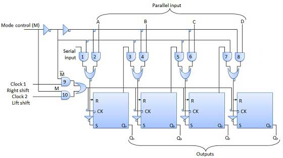
データを一方向にのみシフトできるシフトレジスタを単方向シフトレジスタと呼びます。データを両方向にシフトできるシフトレジスタを双方向シフトレジスタと呼びます。同じロジックを適用して、データを両方向にシフトし、並列にロードできるシフトレジスタは、ユニバーサルシフトレジスタと呼ばれます。シフトレジスタは次の操作を実行できます-
- 並列ロード
- 左シフト
- 右シフト
モード制御入力は、パラレルロード操作の場合はロジック1に接続され、シリアルシフトの場合は0に接続されます。モード制御ピンがグランドに接続されている場合、ユニバーサルシフトレジスタは双方向レジスタとして機能します。シリアルレフト操作の場合、入力は、図に示すANDゲート-1に向かうシリアル入力に適用されます。一方、右シフト操作の場合、シリアル入力はD入力に適用されます。
ブロック図
カウンタは順序回路です。パルスをカウントするために使用されるデジタル回路は、既知のカウンタです。カウンタは、フリップフロップの最も幅広いアプリケーションです。これは、クロック信号が適用されたフリップフロップのグループです。カウンターには2つのタイプがあります。
- 非同期またはリップルカウンター。
- 同期カウンター。
非同期またはリップルカウンター
2ビットリップルアップカウンタの論理図を図に示します。トグル(T)フリップフロップが使用されています。しかし、我々はJでも、JKフリップフロップを使用することができますし、Kは1.外部クロックがフリップフロップAとQのクロック入力に適用されるロジックに恒久的に接続されているAの次のフリップフロップすなわちのクロック入力に印加される出力FF-B。
論理図
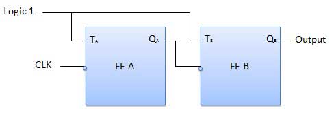
操作
| SN | 状態 | 操作 |
|---|---|---|
| 1 | Initially let both the FFs be in the reset state | Q B Q A = 00最初は |
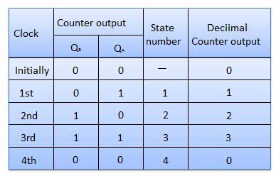
| 2 | After 1st negative clock edge | すぐに第1の負のクロックエッジが印加されるように、FF-Aはトグルし、Q Aは1に等しくなります。 Q Aは、 FF-Bのクロック入力に接続されています。Q Aが0から1に変更されたため、FF-Bではクロックの正のエッジとして扱われます。Qの変化がないBは、 FF-BがFFをトリガした負のエッジであるためです。 Q B Q A = 01最初のクロックパルスの後。 |
| 3 | After 2nd negative clock edge | 2番目の負のクロックエッジが到着すると、FF-Aは再びトグルし、Q A = 0になります。 Q Aの変化は、FF-Bの負のクロックエッジとして機能します。だから、それはまた、トグルし、Q Bは1になります。 Q B Q A = 2番目のクロックパルス後の10。 |
| 4 | After 3rd negative clock edge | 第3負のクロックエッジの到着時に、FF-Aは、再び切り替わり、Q Aが0から1になります。 これは前向きな変化であるため、FF-Bはそれに応答せず、非アクティブのままです。したがって、Q Bは変化せず、引き続き1に等しくなります。 Q B Q A = 3番目のクロックパルス後の11。 |
| 5 | After 4th negative clock edge | 第4の負のクロックエッジの到着時に、FF-Aは、再び切り替わり、Q Aが0から1になります。 Q Aのこの負の変化は、FF-Bのクロックパルスとして機能します。したがって、それはQ変更するトグルBを1から0に。 4番目のクロックパルスの後、Q B Q A = 00。 |
真理値表
同期カウンター
「クロック」パルスがカウンタ内のすべてのフリップフロップに同時に適用される場合、そのようなカウンタは同期カウンタと呼ばれます。
2ビット同期アップカウンター
J AとK A FF-Aの入力は、だから、FF-Aはトグルフリップフロップとして動作するロジック1に関連付けられています。J BおよびK B入力はQに接続されているA。
論理図

操作
| SN | 状態 | 操作 |
|---|---|---|
| 1 | Initially let both the FFs be in the reset state | Q B Q A = 00最初は。 |
| 2 | After 1st negative clock edge | 最初の負のクロックエッジが適用されるとすぐに、FF- Aが切り替わり、QAが0から1に変わります。 ただし、負のクロックエッジの適用の瞬間、Q A、J B = K B = 0。したがって、FF-Bはその状態を変更しません。だから、Q Bは0のままになります。 Q B Q A = 01最初のクロックパルスの後。 |
| 3 | After 2nd negative clock edge | 第二の負のクロックエッジの到着時に、FF-Aは、再び切り替わり、Q Aは、 1から0に変化します。 しかし、この瞬間、Q Aは1でした。したがって、J B = K B = 1であり、FF-Bが切り替わります。したがってQ Bは、 0から1に変化します。 Q B Q A = 2番目のクロックパルス後の10。 |
| 4 | After 3rd negative clock edge | 3番目の立ち下がりクロックエッジを適用すると、FF-Aは0から1に切り替わりますが、FF-Bの状態は変化しません。 Q B Q A = 3番目のクロックパルス後の11。 |
| 5 | After 4th negative clock edge | 次のクロックパルスの印加に、Q AはQとして1から0に変更されますBはまた、1から0に変更されます。 4番目のクロックパルスの後、Q B Q A = 00。 |
カウンターの分類
カウントの進行方法に応じて、同期カウンターまたは非同期カウンターは次のように分類されます。
- アップカウンター
- ダウンカウンター
- アップ/ダウンカウンター
アップ/ダウンカウンター
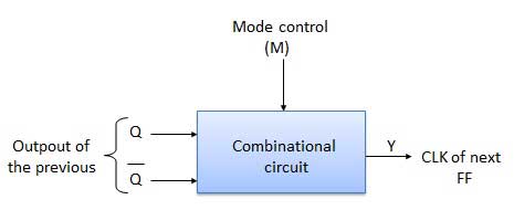
アップカウンタとダウンカウンタを組み合わせて、UP / DOWNカウンタを取得します。アップモードまたはダウンモードを選択するためのモード制御(M)入力も用意されています。アップ/ダウン動作を実現するには、フリップフロップの各ペア間で組み合わせ回路を設計して使用する必要があります。
- アップ/ダウンカウンターの種類
- UP / DOWNリップルカウンター
- UP / DOWN同期カウンター
アップ/ダウンリップルカウンター
UP / DOWNリップルカウンターでは、すべてのFFがトグルモードで動作します。したがって、TフリップフロップまたはJKフリップフロップのいずれかを使用する必要があります。LSBフリップフロップはクロックを直接受信します。ただし、1つおきのFFへのクロックは、前のFFの(Q = Qバー)出力から取得されます。
UP counting mode (M=0)−アップカウントを行う場合は、先行FFのQ出力を次段のクロックに接続します。このモードの場合、モード選択入力Mは論理0(M = 0)にあります。
DOWN counting mode (M=1)− M = 1の場合、前のFFのQバー出力は次のFFに接続されます。これにより、カウンタがカウントモードで動作します。
例
3ビットのバイナリアップ/ダウンリップルカウンタ。
3ビット-したがって、3つのFFが必要です。
UP / DOWN −したがって、モード制御入力は不可欠です。
リップルアップカウンタの場合、先行するFFのQ出力が次のFFのクロック入力に接続されます。
リップルアップカウンタの場合、先行するFFのQ出力が次のFFのクロック入力に接続されます。
リップルダウンカウンタの場合、先行するFFのQバー出力が次のFFのクロック入力に接続されます。
前のFFのQおよびQバー出力の選択は、モード制御入力Mによって制御され、M = 0の場合、UPカウントされます。したがって、QをCLKに接続します。M = 1の場合、ダウンカウント。したがって、QバーをCLKに接続します。
ブロック図
真理値表
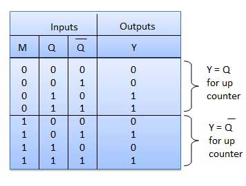
操作
| SN | 状態 | 操作 |
|---|---|---|
| 1 | Case 1 − With M = 0 (Up counting mode) | M = 0およびMbar = 1の場合、図1のANDゲート1および3。ANDゲート2と4は無効になりますが、有効になります。 したがってQ Aは、 FF-BおよびQのクロック入力に接続されますBがFF-Cのクロック入力に接続されます。 これらの接続は、通常のアップカウンターの接続と同じです。したがって、M = 0の場合、回路はアップカウンタとして機能します。 |
| 2 | Case 2: With M = 1 (Down counting mode) | M = 1の場合、図のANDゲート2と4。ANDゲート1と3が無効になっているのに対し、は有効になっています。 したがってQ Aバーは、FF-BおよびQのクロック入力に接続されますB FF-Cのクロック入力に接続されますバー。 これらの接続により、ダウンカウンターが生成されます。したがって、M = 1の場合、回路はダウンカウンタとして機能します。 |
モジュラスカウンター(MOD-Nカウンター)
2ビットのリップルカウンタはMOD-4カウンタと呼ばれ、3ビットのリップルカウンタはMOD-8カウンタと呼ばれます。したがって、一般に、nビットのリップルカウンターはモジュロNカウンターと呼ばれます。ここで、MOD番号= 2n。
モジュラスのタイプ
- 2ビットアップまたはダウン(MOD-4)
- 3ビットアップまたはダウン(MOD-8)
- 4ビットアップまたはダウン(MOD-16)
カウンターの適用
- 周波数カウンター
- デジタル時計
- 時間測定
- A / Dコンバータ
- 分周回路
- デジタル三角波発生器。
記憶は人間の脳のようなものです。データと命令を格納するために使用されます。コンピュータメモリは、データが処理され、処理に必要な命令が格納されるコンピュータのストレージスペースです。
メモリは多数の小さな部分に分割されています。各部分はセルと呼ばれます。各場所またはセルには、0からメモリサイズから1を引いた値まで変化する一意のアドレスがあります。
たとえば、コンピュータに64kワードがある場合、このメモリユニットには64 * 1024 = 65536のメモリ位置があります。これらの場所のアドレスは0から65535まで変化します。
メモリには主に2つのタイプがあります
Internal Memory −キャッシュメモリとプライマリ/メインメモリ
External Memory −磁気ディスク/光ディスクなど
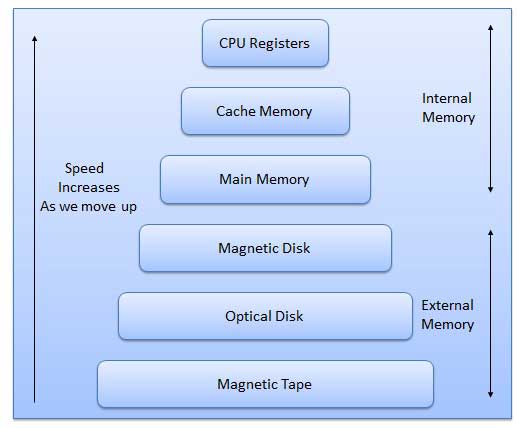
上から下に行くと、メモリ階層の特徴は次のとおりです。
- ストレージの容量が増加します。
- ストレージのビットあたりのコストが減少します。
- CPUによるメモリへのアクセス頻度が減少します。
- CPUによるアクセス時間が長くなります。
羊
RAMは、データ、プログラム、およびプログラム結果を格納するためのCPUの内部メモリを構成します。読み取り/書き込みメモリです。これはランダムアクセスメモリ(RAM)と呼ばれます。
RAMのアクセス時間はワードのアドレスに依存しないため、メモリ内の各ストレージの場所は他の場所と同じように簡単にアクセスでき、同じ時間がかかります。私たちはランダムにそして非常に速くメモリに到達することができますが、かなり高価になることもあります。
RAMは揮発性です。つまり、コンピュータの電源を切ったとき、または電源障害が発生した場合、RAMに保存されているデータは失われます。したがって、バックアップの無停電電源装置(UPS)がコンピューターでよく使用されます。RAMは、物理的なサイズと保持できるデータ量の両方の点で小さいです。
RAMには2つのタイプがあります
- スタティックRAM(SRAM)
- ダイナミックRAM(DRAM)
スタティックRAM(SRAM)
言葉 static indicates that the memory retains its contents as long as power remains applied. However, data is lost when the power gets down due to volatile nature. SRAM chips use a matrix of 6-transistors and no capacitors. Transistors do not require power to prevent leakage, so SRAM need not have to be refreshed on a regular basis.
Because of the extra space in the matrix, SRAM uses more chips than DRAM for the same amount of storage space, thus making the manufacturing costs higher.
Static RAM is used as cache memory needs to be very fast and small.
Dynamic RAM (DRAM)
DRAM, unlike SRAM, must be continually refreshed in order for it to maintain the data. This is done by placing the memory on a refresh circuit that rewrites the data several hundred times per second. DRAM is used for most system memory because it is cheap and small. All DRAMs are made up of memory cells. These cells are composed of one capacitor and one transistor.
ROM
ROM stands for Read Only Memory. The memory from which we can only read but cannot write on it. This type of memory is non-volatile. The information is stored permanently in such memories during manufacture.
A ROM, stores such instruction as are required to start computer when electricity is first turned on, this operation is referred to as bootstrap. ROM chip are not only used in the computer but also in other electronic items like washing machine and microwave oven.
Following are the various types of ROM −
MROM (Masked ROM)
The very first ROMs were hard-wired devices that contained a pre-programmed set of data or instructions. These kind of ROMs are known as masked ROMs. It is inexpensive ROM.
PROM (Programmable Read Only Memory)
PROM is read-only memory that can be modified only once by a user. The user buys a blank PROM and enters the desired contents using a PROM programmer. Inside the PROM chip there are small fuses which are burnt open during programming. It can be programmed only once and is not erasable.
EPROM (Erasable and Programmable Read Only Memory)
The EPROM can be erased by exposing it to ultra-violet light for a duration of upto 40 minutes. Usually, an EPROM eraser achieves this function. During programming an electrical charge is trapped in an insulated gate region. The charge is retained for more than ten years because the charge has no leakage path. For erasing this charge, ultra-violet light is passed through a quartz crystal window (lid). This exposure to ultra-violet light dissipates the charge. During normal use the quartz lid is sealed with a sticker.
EEPROM (Electrically Erasable and Programmable Read Only Memory)
The EEPROM is programmed and erased electrically. It can be erased and reprogrammed about ten thousand times. Both erasing and programming take about 4 to 10 ms (millisecond). In EEPROM, any location can be selectively erased and programmed. EEPROMs can be erased one byte at a time, rather than erasing the entire chip. Hence, the process of re-programming is flexible but slow.
Serial Access Memory
Sequential access means the system must search the storage device from the beginning of the memory address until it finds the required piece of data. Memory device which supports such access is called a Sequential Access Memory or Serial Access Memory. Magnetic tape is an example of serial access memory.
Direct Access Memory
Direct access memory or Random Access Memory, refers to conditions in which a system can go directly to the information that the user wants. Memory device which supports such access is called a Direct Access Memory. Magnetic disks, optical disks are examples of direct access memory.
Cache Memory
Cache memory is a very high speed semiconductor memory which can speed up CPU. It acts as a buffer between the CPU and main memory. It is used to hold those parts of data and program which are most frequently used by CPU. The parts of data and programs, are transferred from disk to cache memory by operating system, from where CPU can access them.
Advantages
- Cache memory is faster than main memory.
- It consumes less access time as compared to main memory.
- It stores the program that can be executed within a short period of time.
- It stores data for temporary use.
Disadvantages
- Cache memory has limited capacity.
- It is very expensive.
Virtual memory is a technique that allows the execution of processes which are not completely available in memory. The main visible advantage of this scheme is that programs can be larger than physical memory. Virtual memory is the separation of user logical memory from physical memory.
This separation allows an extremely large virtual memory to be provided for programmers when only a smaller physical memory is available. Following are the situations, when entire program is not required to be loaded fully in main memory.
User written error handling routines are used only when an error occurred in the data or computation.
Certain options and features of a program may be used rarely.
Many tables are assigned a fixed amount of address space even though only a small amount of the table is actually used.
The ability to execute a program that is only partially in memory would counter many benefits.
Less number of I/O would be needed to load or swap each user program into memory.
A program would no longer be constrained by the amount of physical memory that is available.
Each user program could take less physical memory, more programs could be run the same time, with a corresponding increase in CPU utilization and throughput.
Auxiliary Memory
Auxiliary memory is much larger in size than main memory but is slower. It normally stores system programs, instruction and data files. It is also known as secondary memory. It can also be used as an overflow/virtual memory in case the main memory capacity has been exceeded. Secondary memories cannot be accessed directly by a processor. First the data/information of auxiliary memory is transferred to the main memory and then that information can be accessed by the CPU. Characteristics of Auxiliary Memory are following −
Non-volatile memory − Data is not lost when power is cut off.
Reusable − The data stays in the secondary storage on permanent basis until it is not overwritten or deleted by the user.
Reliable − Data in secondary storage is safe because of high physical stability of secondary storage device.
Convenience − With the help of a computer software, authorised people can locate and access the data quickly.
Capacity − Secondary storage can store large volumes of data in sets of multiple disks.
Cost − It is much lesser expensive to store data on a tape or disk than primary memory.
Microprocessing unit is synonymous to central processing unit, CPU used in traditional computer. Microprocessor (MPU) acts as a device or a group of devices which do the following tasks.
- communicate with peripherals devices
- provide timing signal
- direct data flow
- perform computer tasks as specified by the instructions in memory
8085 Microprocessor
The 8085 microprocessor is an 8-bit general purpose microprocessor which is capable to address 64k of memory. This processor has forty pins, requires +5 V single power supply and a 3-MHz single-phase clock.
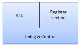
Block Diagram
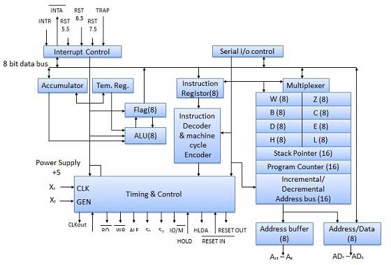
ALU
The ALU perform the computing function of microprocessor. It includes the accumulator, temporary register, arithmetic & logic circuit & and five flags. Result is stored in accumulator & flags.
Block Diagram
Accumulator
It is an 8-bit register that is part of ALU. This register is used to store 8-bit data & in performing arithmetic & logic operation. The result of operation is stored in accumulator.
Diagram

Flags
Flags are programmable. They can be used to store and transfer the data from the registers by using instruction. The ALU includes five flip-flops that are set and reset according to data condition in accumulator and other registers.
S (Sign) flag − After the execution of an arithmetic operation, if bit D7 of the result is 1, the sign flag is set. It is used to signed number. In a given byte, if D7 is 1 means negative number. If it is zero means it is a positive number.
Z (Zero) flag − The zero flag is set if ALU operation result is 0.
AC (Auxiliary Carry) flag − In arithmetic operation, when carry is generated by digit D3 and passed on to digit D4, the AC flag is set. This flag is used only internally BCD operation.
P (Parity) flag − After arithmetic or logic operation, if result has even number of 1s, the flag is set. If it has odd number of 1s, flag is reset.
C (Carry) flag − If arithmetic operation result is in a carry, the carry flag is set, otherwise it is reset.
Register section
It is basically a storage device and transfers data from registers by using instructions.
Stack Pointer (SP) − The stack pointer is also a 16-bit register which is used as a memory pointer. It points to a memory location in Read/Write memory known as stack. In between execution of program, sometime data to be stored in stack. The beginning of the stack is defined by loading a 16-bit address in the stack pointer.
Program Counter (PC) − This 16-bit register deals with fourth operation to sequence the execution of instruction. This register is also a memory pointer. Memory location have 16-bit address. It is used to store the execution address. The function of the program counter is to point to memory address from which next byte is to be fetched.
Storage registers − These registers store 8-bit data during a program execution. These registers are identified as B, C, D, E, H, L. They can be combined as register pair BC, DE and HL to perform some 16 bit operations.
Time and Control Section
This unit is responsible to synchronize Microprocessor operation as per the clock pulse and to generate the control signals which are necessary for smooth communication between Microprocessor and peripherals devices. The RD bar and WR bar signals are synchronous pulses which indicates whether data is available on the data bus or not. The control unit is responsible to control the flow of data between microprocessor, memory and peripheral devices.
PIN diagram
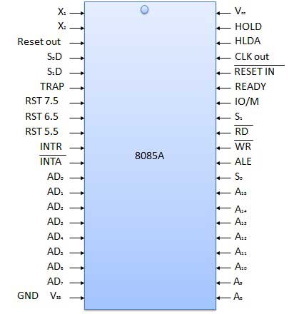
All the signal can be classified into six groups
| S.N. | Group | Description |
|---|---|---|
| 1 | Address bus | The 8085 microprocessor has 8 signal line, A15 - A8 which are uni directional and used as a high order address bus. |
| 2 | Data bus | The signal line AD7 - AD0 are bi-directional for dual purpose. They are used as low order address bus as well as data bus. |
| 3 | Control signal and Status signal | Control Signal RD bar − It is a read control signal (active low). If it is active then memory read the data. WR bar − It is write control signal (active low). It is active when written into selected memory. Status signal ALU (Address Latch Enable) − When ALU is high. 8085 microprocessor use address bus. When ALU is low. 8085 microprocessor is use data bus. IO/M bar − This is a status signal used to differentiate between i/o and memory operations. When it is high, it indicate an i/o operation and when it is low, it indicate memory operation. S1 and S0 − These status signals, similar to i/o and memory bar, can identify various operations, but they are rarely used in small system. |
| 4 | Power supply and frequency signal | Vcc − +5v power supply. Vss − ground reference. X, X − A crystal is connected at these two pins. The frequency is internally divided by two operate system at 3-MHz, the crystal should have a frequency of 6-MHz. CLK out − This signal can be used as the system clock for other devices. |
| 5 | Externally initiated signal | INTR (i/p) − Interrupt request. INTA bar (o/p) − It is used as acknowledge interrupt. TRAP (i/p) − This is non maskable interrupt and has highest priority. HOLD (i/p) − It is used to hold the executing program. HLDA (o/p) − Hold acknowledge. READY (i/p) − This signal is used to delay the microprocessor read or write cycle until a slow responding peripheral is ready to accept or send data. RESET IN bar − When the signal on this pin goes low, the program counter is set to zero, the bus are tri-stated, & MPU is reset. RESET OUT − This signal indicate that MPU is being reset. The signal can be used to reset other devices. RST 7.5, RST 6.5, RST 5.5 (Request interrupt) − It is used to transfer the program control to specific memory location. They have higher priority than INTR interrupt. |
| 6 | Serial I/O ports | The 8085 microprocessor has two signals to implement the serial transmission serial input data and serial output data. |
Instruction Format
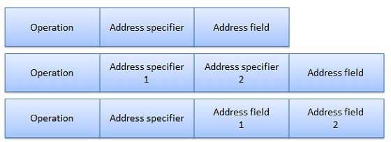
Each instruction is represented by a sequence of bits within the computer. The instruction is divided into group of bits called field. The way instruction is expressed is known as instruction format. It is usually represented in the form of rectangular box. The instruction format may be of the following types.
Variable Instruction Formats
These are the instruction formats in which the instruction length varies on the basis of opcode & address specifiers. For Example, VAX instruction vary between 1 and 53 bytes while X86 instruction vary between 1 and 17 bytes.
Format

Advantage
These formats have good code density.
Drawback
These instruction formats are very difficult to decode and pipeline.
Fixed Instruction Formats
In this type of instruction format, all instructions are of same size. For Example, MIPS, Power PC, Alpha, ARM.
Format

Advantage
They are easy to decode & pipeline.
Drawback
They don't have good code density.
Hybrid Instruction Formats
In this type of instruction formats, we have multiple format length specified by opcode. For example, IBM 360/70, MIPS 16, Thumb.
Format
Advantage
These compromise between code density & instruction of these type are very easy to decode.
Addressing Modes
Addressing mode provides different ways for accessing an address to given data to a processor. Operated data is stored in the memory location, each instruction required certain data on which it has to operate. There are various techniques to specify address of data. These techniques are called Addressing Modes.
Direct addressing mode − In the direct addressing mode, address of the operand is given in the instruction and data is available in the memory location which is provided in instruction. We will move this data in desired location.
Indirect addressing mode − In the indirect addressing mode, the instruction specifies a register which contain the address of the operand. Both internal RAM and external RAM can be accessed via indirect addressing mode.
Immediate addressing mode − In the immediate addressing mode, direct data is given in the operand which move the data in accumulator. It is very fast.
Relative addressing mode − In the relative address mode, the effective address is determined by the index mode by using the program counter in stead of general purpose processor register. This mode is called relative address mode.
Index addressing mode − In the index address mode, the effective address of the operand is generated by adding a content value to the contents of the register. This mode is called index address mode.